












Table of Contents
What is the most reliable way to prevent thermostat wiring errors in hydronic underfloor heating?
2-wire non-polarity BUS technology eliminates reversed polarity errors entirely. Instead of training installers to distinguish line from load, this approach removes the decision point at the hardware level — either wire can be connected to either terminal.
- No polarity sensitivity — either wire to either terminal
- Reduces installation time and rework costs
- Eliminates the most common class of UFH wiring faults
Introduction
Thermostat wiring errors are a persistent problem in hydronic underfloor heating installations. A single reversed polarity connection — swapping the line and load wires — can destroy a control board, delay a project, and generate expensive rework costs.
These errors occur not because installers are careless, but because traditional wiring schemes require them to distinguish between polarity-sensitive terminals. In tight spaces, poor lighting, or under time pressure, mistakes happen.
This article examines the root causes of thermostat wiring errors in hydronic underfloor heating systems and presents a practical solution: 2-wire non-polarity BUS technology. Rather than relying on training and manual verification to reduce error rates, this approach eliminates the possibility of wiring errors at the hardware level.
Key insight: The most effective way to reduce wiring errors is not to improve installer training, but to eliminate the conditions that make errors possible. 2-wire non-polarity BUS technology does exactly that.
- Removes polarity sensitivity at the hardware level
- Reduces installation time and material costs
- Eliminates the most common class of UFH wiring faults
Why Errors Occur in Hydronic Heating
Hydronic underfloor heating systems present several conditions that make wiring errors more likely:
Multiple zones, multiple terminations
A typical UFH system may include 4, 6, or 8 separate thermostats, each requiring correct wiring to the wiring centre. With every connection representing a potential error point, the probability of at least one incorrect termination increases with system scale.
Installers are not always electricians
UFH systems are commonly installed by plumbers or heating engineers — professionals who understand hydronic systems but may have limited experience with low-voltage polarity-sensitive wiring.
Constrained working conditions
Wiring centres are often installed in cupboards, plant rooms, or other confined spaces where terminal labels are difficult to read. These conditions increase the likelihood of misidentifying line and load terminals.
Retrofit projects add uncertainty
Existing wiring may be unlabelled, incorrectly coloured, or degraded, making it difficult to determine which wire is which. The problem becomes a guessing game. The installer chooses a pair of wires and hopes it is correct.
When an installer connects a line wire to a load terminal — or reverses the two — the thermostat may fail to power on, operate intermittently, or sustain permanent damage to the control board. The outcome is always the same: rework.
The Cost of a Wiring Error
The direct costs are straightforward:
- Replacement of a damaged thermostat
- Service call for diagnosis and rework
- Project delay while replacement parts are procured
Note: The actual cost varies significantly by region and project type. In the UK and Ireland, a single wiring error typically results in at least one additional site visit, plus the cost of replacement parts. For a detailed cost estimate, consult local service providers.
The indirect costs are often larger:
- Delays to subsequent trades waiting for the system to be operational
- Damage to the installer's reputation with the general contractor
- Risk of callbacks for intermittent faults caused by marginal connections
These costs are avoidable.
A Better Approach: Design Out the Error
The most effective way to reduce wiring errors is not to improve installer training, but to eliminate the conditions that make errors possible.
This principle — designing out points of failure rather than training people to avoid them — is the logic behind 2-wire non-polarity BUS technology.
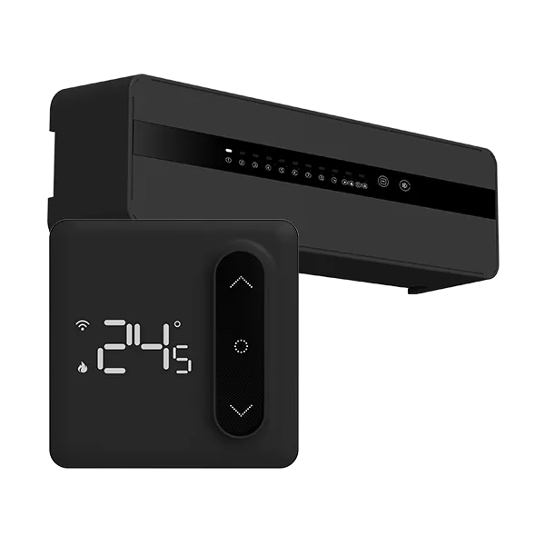
A non-polarity BUS system uses a single pair of wires to deliver both power and communication between the thermostat and the wiring centre. The connection is polarity-insensitive: either wire can be connected to either terminal.
| Feature | Traditional Polarity-Dependent Wiring | 2-Wire Non-Polarity BUS |
|---|---|---|
| Wires required | 3–8 | 2 |
| Polarity sensitivity | Yes | No |
| Connection logic | Line to L, load to LOAD | Either wire to either terminal |
| Electrician required | Often | No |
| Rework from polarity errors | Possible | Eliminated |
How It Works
The two wires in a non-polarity BUS system serve a dual function: they carry power from the wiring centre to the thermostat, and they enable two-way data communication between devices.
Because the communication protocol does not require a specific polarity, the system can function correctly regardless of which wire connects to which terminal. The wiring centre detects the thermostat's presence and establishes communication automatically.
This is not a new technology — BUS communication has been used in building automation for years. Its application to hydronic underfloor heating is a more recent development, enabled by control hardware designed specifically for this purpose.
Practical Implications for Installers
The difference in installation procedure is straightforward:
Traditional wiring:
- Identify line (power) wire — typically black or red
- Identify load (heater) wire — often white or blue
- Connect line to the "L" or power terminal
- Connect load to the "LOAD" or heating terminal
- Verify correct termination
- Power on and test
With non-polarity BUS:
- Take the two wires from the wall or wiring centre
- Connect either wire to either terminal
- Power on
The reduction in termination time is significant. More importantly, the installer does not need to make a decision about which wire goes where — so the decision cannot be wrong.
Additional Benefits Beyond Error Elimination
2-wire non-polarity BUS offers several secondary advantages:
Lower material costs
Only two-core cable is required, compared with 3–8 cores for conventional thermostats.
Simplified inventory management
A single cable type serves all thermostats in the system.
Two-way communication
The BUS protocol enables the wiring centre to receive data from each thermostat, supporting remote monitoring and system diagnostics.
Reduced training requirements
Installers do not need to learn colour codes or terminal assignments for each thermostat model. The wiring process is the same for all zones.
Limitations and Considerations
Non-polarity BUS does not eliminate all wiring errors. Physical damage to cables, loose connections, and incorrect cable sizing can still cause problems. However, it eliminates the specific class of error caused by reversed polarity — which accounts for a substantial portion of UFH wiring faults.
The technology requires compatible thermostats and wiring centres. For new installations or full system replacements, specifying non-polarity BUS components is straightforward. For partial upgrades, compatibility with existing hardware must be verified.
Note: For specific compatibility information, refer to product documentation or contact the manufacturer.
Technical Specifications
For installers and system designers requiring detailed technical information:
| Specification | Detail |
|---|---|
| BUS topology | 2-wire, non-polarity |
| Communication protocol | BUS, optimized for hydronic control |
| Max cable length | 100m per bus segment (typical installation) |
| Max zones per controller | 8 |
| Communication cycle | Real-time, continuous polling |
| EMC compliance | EN60730 |
| Cable type | Standard 2-core (0.75mm²–1.5mm²) |
Conclusion
Thermostat wiring errors are a common source of rework in hydronic underfloor heating installations. The conventional response is to improve installer training and verification procedures — but errors persist because the wiring scheme itself requires installers to make polarity-sensitive decisions under working conditions that are often less than ideal.
2-wire non-polarity BUS technology addresses the problem at its source. By eliminating the need to distinguish between line and load connections, it removes the possibility of reversed polarity errors. The result is fewer rework visits, lower project costs, and more reliable system operation.
For installers, developers, and OEMs seeking to reduce installation defects in hydronic heating projects, this technology offers a practical and proven solution.